

How To Repair Idle Up For Pto On Chev 5500 Truck
Chevrolet-GMC Diesel Diagnostics
2011-2016 6.6 L | 2007.5-2010 6.6 L | 2001-2007 6.6 L | 6.5 L DS Pump | 1982-1993 GM/Ford IDI
2011-2016 6.6L LML – LGH Duramax
PDF: 2011 – 2016 6.6L LML/LGH Duramax
In order to do proper diagnostics you will need a scan tool, diagnostic service information and some special tools such as a vacuum test gauge J44638 (OTC 6754) available from GM Special Tools or Freedom Racing Tool and Equipment. Also note that 1 MPa (megapascal) is equal to approximately 145 PSI, 100 kpa is about 14.5 PSI.
If you don't have service information you can buy a subscription online at alldatadiy.com or eAutorepair.net.
Piezo High Pressure Common Rail Basic Information
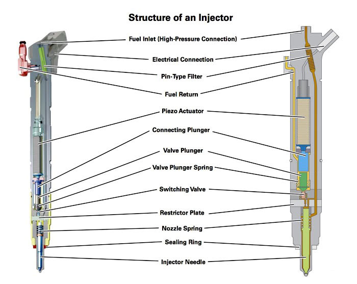
The high pressure pump builds rail pressure and delivers it to the fuel rail manifold where it flows through the injector lines to the injectors. The fuel pressure regulator in the high pressure pump and the pressure regulating valve in the rail control rail pressure. The injectors have a piezo stack instead of an electro-magnetic solenoid. When energized, the piezo crystals expand, lifting the control valve off of its seat via a hydraulic coupler (connecting plunger below) to begin injection. If the valve seat in the injector is leaking or the pressure regulating valve leaks then it will not build enough rail pressure to start the engine.

The fuel tank (5) stores the fuel supply. A mechanical high pressure fuel injection pump (13), located below the engine intake, includes the fuel supply pump and the high-pressure pump. Fuel is drawn through the diesel fuel conditioning module (8), which combines a water separator, hand operated fuel prime pump, filter element and then through a fuel filter vacuum switch (9) to the fuel injection pump. The engine control module (ECM) controls the fuel pump pressures by using two fuel pressure regulators, fuel pressure regulator 1 is located on top of the fuel injection pump and fuel pressure regulator 2 (7) is located on a fuel rail (2). The fuel pressure sensor (4) provides a voltage signal to the ECM to indicated fuel rail pressures. The high pressure fuel is supplied to the fuel injectors (1) through separate high pressure pipes. The fuel injectors supply fuel directly to the combustion chambers of the engine. The fuel that is not injected into the combustion chamber is used to help lubricate and cool the injector and is routed back to the fuel tank. The fuel injector return line pressure regulator (14) maintains fuel pressure on the return side of the fuel injectors. This is required for proper fuel injector operation. In the event the vehicle runs out of fuel a check valve (11) in the exhaust aftertreatment fuel injector (10) supply line opens and the fuel supply pump back fills the return side with fuel. (Courtesy GM)
CAUTION
The fuel system contains high pressure fuel up to 29,000 PSI. Do not use you fingers to find fuel leaks! High pressure fuel entering your bloodstream may result in amputation or loss of life.
Check and record any DTC, look at snap shot data or save, do not erase codes prior to doing repairs, you will erase the snapshot and other relevant data.
No Start or Hard Start
- Confirm actual versus desired rail pressure even under crank no start conditions, to confirm the starting issue is rail pressure related. If rail pressure matches desired, diagnose other codes that may be related to starting problems.
- Use a vacuum gauge to check the suction side of the fuel system. You should have no more than 5 inches Hg at WOT (wide open throttle) or 7-8 inches Hg under load. If you still have too much restriction after changing the filter, check for collapsing soft fuel lines by the drivers side valve cover and under the truck near the transmission. The fuel tank pick up may also be plugged. Too little vacuum (less than 2 inches Hg) means that it could be sucking air.
- Check for air in fuel system; install clear lines before and after the filter housing to check for air in the lines.
- Verify the fuel injector return line pressure is greater than 3 BAR (see "Fuel Injectors" for more information). Buy LML Injector Return Rail
- Check the injector returns. Doing this correctly requires special tools. See GM service information. If everything else checks OK, they can also be sent in for testing. Buy Bosch LML or LGH Injectors. Injector Testing Information.
- (No Start) Disconnect the electrical connector and return line from one injector. Plug the fuel return line fitting with a suitable tool (CH-50377-A). Crank the engine for 15 seconds and verify no fuel leaks from the injector. If fuel leaks from the injector, replace it. Repeat for all eight injectors.
- (Hard start but runs) Disconnect the return line from one injector. Plug the fuel return line fitting with a suitable tool (CH-50377-A). Use adapter CH-50378 (required to accurately test return, contains regulator to maintain injector return pressure) to route the injector return into a graduated container. Crank or idle the engine until fuel is dripping out of the line. Crank or idle the engine for 15 seconds and measure the return quantity. If the quantity is greater than 3 ml in 15 seconds, replace it. Repeat for all eight injectors.
- Remove the return hose from the fuel pressure regulator 2 (pressure control valve in left hand rail) and plug the hose. Crank the engine for 15 seconds and measure the fuel from the regulator. The volume of fuel should be less than 10 ml. If it is more, replace the regulator. The high pressure seal on the pressure control valve is one time use. Do not remove the pressure control valve unless you are sure it is defective and you are replacing it. Buy Fuel Pressure Regulator 2
- Unplug the fuel pressure regulator 2 (pressure control valve in left hand rail) electrical connector. Crank the engine for 15 seconds and verify there is a steady flow of fuel from the fitting on the rail. If there is not, proceed to checking/replacing the high pressure pump.
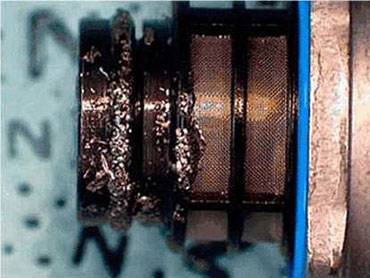
- Remove the high pressure regulator from the high pressure pump and check for metal debris. If there is metal found, the entire high pressure fuel system must be checked for metal and replaced as needed. GM recommends replacing the injection pump, rails, high pressure fuel lines, fuel injectors, fuel return rails, indirect fuel injector, and indirect injector fuel feed tubes if metal is found.(See picture under High Pressure Pump). Buy LML LGH Fuel System Repair Parts
Black Smoke
****Diagnosing smoke related issues on trucks equipped with diesel particulate filters may require temporarily disconnecting the filter or installing a test pipe to see the smoke. Excessive smoke from the tailpipe with a DPF installed usually means the DPF is damaged and may need replaced.
- If at idle, use the scan tool to cut out one cylinder at a time and see if the smoke disappears.
- Dirty air filter
- Exhaust leaks or Boost leaks, you can usually hear a boost leak as a high pitched squeal or unusual rushing or whooshing air sound under load.
- Inspect the mass air flow (MAF) sensor for obstruction, contamination, and damage.
- Inspect for the EGR valve sticking open. Command the valve to 20%. Desired and actual position should not be more than 3% different.
Misses – Cuts Out
- Use scan tool to isolate one cylinder at a time. Monitor injector balance rates in park or neutral. Injector balance rates outside of +4 to -6.9 indicate a problem with that cylinder or injector.
- A missing or damaged chamber gasket or low compression could cause a miss.
- Crankcase overfull (fuel dilution) can cause a rough run and balance rates out of specification.
- Inspect the CKP sensor reluctor wheel. Remove the CKP sensor and attempt to move the reluctor wheel front to back or side to side with a probe. If there is any movement, the reluctor wheel retaining bolts are loose.
- Inspect for an intermittent FRP sensor signal by wiggling the harness between the sensor and the ECM with the ignition ON and the engine OFF, while monitoring the parameter with a scan tool.
Knock
- Use scan tool to isolate one cylinder at a time. Monitor injector balance rates in park or neutral. Injector balance rates outside of +4 to -6.9 indicate a problem with that cylinder or injector.
- Use cap off tools to block off one injector at a time.
- A slight knock can start occurring due to injector problems, often after a contaminated fuel problem.
Surge or Lope at idle
- Fuel pressure regulator: Map actual versus desired rail pressure, if the graph has a "shark tooth" pattern and there is no air in the system, it is usually caused by a bad fuel pressure regulator.
- Inspect for an intermittent FRP sensor signal by wiggling the harness between the sensor and the ECM with the ignition ON and the engine OFF, while monitoring the parameter with a scan tool.
- Air in the fuel system (see fuel supply and filter housing section)
- Inspect the CKP sensor reluctor wheel. Remove the CKP sensor and attempt to move the reluctor wheel front to back or side to side with a probe. If there is any movement, the reluctor wheel retaining bolts are loose.
White or blue smoke at idle
****Diagnosing smoke related issues on trucks equipped with diesel particulate filters may require temporarily disconnecting the filter or installing a test pipe to see the smoke. Excessive smoke from the tailpipe with a DPF installed usually means the DPF is damaged and may need replaced.
If the smoke clears in less than 1 minute, this could be normal depending on temperature and altitude. Blue white smoke that burns your eyes is un-burnt fuel; cold temperatures, high altitude and excessive idle time all mean cold combustion and white smoke.
- Possible bad injector, use the scan tool to cancel one cylinder at a time and see if the smoke clears up. However, using the scan tool to kill the injector does not reduce rail pressure in the injector and the tip can still leak fuel, cap off lines one at a time to pinpoint injector. Also look at the balance rates, if the tip is leaking fuel then the balance rates may be out of specification. Try increasing the rail pressure, we find injector nozzles may leak at idle pressure, but do not leak at higher pressure.
- Check glow plug operation when cold.
- Check rail pressure when engine is off, it should 0 PSI.
- Inspect the engine coolant temperature (ECT) sensor. Use the scan tool in order to compare the ECT with the ambient air temperature on a cold engine. The readings should be within 5 degrees on one another.
- Check the coolant level in the reservoir. White coolant smoke may be mistaken for blue/gray smoke. If the coolant level is low, diagnose the cooling system. Coolant smoke will smell sweet and not burn your eyes like fuel smoke.
- Excessive idle time can cause white smoke when cold due to carbon build up on injector tips. More than 20% idle time is excessive. If the injectors have excessive carbon on the nozzle tip then balance rates should be high on that cylinder.
- Per GM TSB PI0235D, loose and/or misaligned exhaust clamp joints at the turbo downpipe can cause white smoke, a fuel smell, and fluid on the exhaust system. This is due to the fuel from the hydrocarbon injector (HCI) leaking from the joints.
Dilution
- Some dilution is normal for DPF equipped engines. Regeneration cycles will cause some fuel to leak past the piston rings in the cylinder and drain into the oil. Normal oil change intervals are critical for this reason. LML engines use a "Hydrocarbon Injector", AKA "9th Injector", to inject fuel directly into the exhaust stream post turbo. This helps greatly to extend engine oil life.
- Leak at the high pressure pump drive shaft seal.
Fuel Supply and Fuel Filter Housing
The fuel filter housing (AKA fuel conditioning module in GM literature) is on the suction side (there is not a fuel supply pump from the factory on pick ups) and are prone to suck air. The 2011 and newer trucks are equipped with a "fuel filter pressure switch" that will open and trigger a "Fuel Filter Restricted" message in the IPC (instrument panel cluster) when supply restriction reaches 14". Follow the GM fuel system diagnosis in the service manual.
- Install fuel vacuum test tool.
- Prime the fuel system with the hand primer until 10 PSI is indicated on the gauge, check for external leaks and repair. If the pressure drops from 10 PSI to 2 PSI in less than 1 minute, remove the fuel outlet line from the filter and cap it. Remove the ignition 1 relay and crank the engine for 2 – 15 second intervals, the high pressure pump should pull at least 12 inches of Hg vacuum. If air gets into the system it will cause a false/low reading.
- Install clear hoses at the inlet and outlet of the fuel filter housing. Re-prime the system and then start the engine, there should be very little air going into or coming out of the fuel filter housing.
- Common air ingestion places are the filter housing, drain valve, rubber hoses and quick connections. You need to use clear lines to isolate where the air is coming from and work your way back toward the tank until you don't have any more air coming through the clear line. Unless you know where to get the tool that sees through black rubber lines to find air, your only other option is to bounce around and replace parts.
High Pressure Injection Pump (CP4.2 Pump)
Note: The CP4.2 pumps are not as durable as the CP3 pumps. Poor fuel supply, contamination, and/or running them out of fuel (plugged fuel filter) will cause them to fail. When they fail it is often catastrophic and they send metal particles throughout the high pressure side of the fuel system, causing further damage.
Check the fuel supply system first: see "Fuel Supply" above.
- Before condemning the pump for a starting issue you need to be certain that the high pressure fuel system is not leaking the pressure. Check the injector return and the pressure control valve in the fuel rail.
- If there has been a major contamination issue with dirt and or water then it is very likely that the high pressure pump will need to be replaced. The injectors are typically damaged as well if the pump is damaged.
- If the pump will not build the desired pressure while cranking and everything else checks OK, remove the regulator from the pump and inspect for metal (see picture below). If there is metal debris, the entire fuel system will need to be cleaned and/or replaced. Buy CP4 Injection Pump
- Other CP4 Notes:
- The CP4 pump gear must be timed properly when installed in the engine.
(Courtesy GM)
Fuel Injectors
Note: The injectors are a piezo type CR injector (see first page). Diagnosis is much different than the earlier generations.
The engine control module (ECM) supplies a high voltage supply circuit and a high voltage control circuit for each fuel injector. The injector high voltage supply circuit and the high voltage control circuit are both controlled by the ECM. The ECM energizes each fuel injector by grounding the control circuit and supplying each fuel injector with up to 250 V and 20 amps on the voltage supply circuit to activate the piezo type fuel injectors. This is controlled by boost capacitors in the ECM. During the 250 V boost phase the capacitor is used to charge the injector piezo stack allowing for injector opening. The injector is then held open with this high voltage. At the end of the injection event the ECM closes the injector by discharging the injector piezo stack.
- The injectors are cooled by a calibrated amount of fuel flow through the injector body to the injector return lines. If the injectors are worn, damaged, or contaminated, the amount of fuel flowing through the injector body may increase, resulting in improper injector performance. The maximum allowable leakage for one injector is 3 ml in 15 seconds, cranking or at idle.
- The injectors require a minimum of 3 BAR (45 psi) of pressure in the return system. Pressure is maintained via a "Constant Pressure Regulator" at 4-11 BAR (58-160 PSI).
- Other Injector Notes
- Balance Rates, when checked in Park or Neutral, should indicate bad injectors. Any injectors that are more than +4/-6.9 are a possible cause for rough run.
- Miss, smoke or rough run usually indicate that the injectors are the cause. LML engines with a DPF may not show any smoke, but frequent DPF regen events would suggest poor combustion.
- We have seen a couple of vehicles that do not have starting issues, but injector return is excessive at higher rail pressures which may cause the P0087 to set.
- When replacing the injectors, the "Fuel Injector Correction Reset" must be done. If not, a P026D code may set.
- Buy New or Reman Bosch LML Injectors
Turbo
- LML turbos have a vane position sensor, check actual versus desired.
- Vane position sensor codes indicate sticky or stuck vanes, unison ring wear, VGT actuator failure, restricted oil supply, or a VGT position sensor failure. The design of these turbos is nearly identical to 6.0l Powerstroke turbos which are known for this type of failure. The turbos may free up at higher rpm due in part to additional oil pressure/volume to drive the vane actuator piston. Stuck unison rings are much more common than actuator or position sensor failures in our experience, and can happen in as few as 40,000 miles. Buy New Garrett LML Turbo
Diesel Exhaust Fluid
Diesel exhaust fluid (DEF), AKA reductant or urea, is injected into the exhaust gases prior to entering the SCR (selective catalyst reduction) stage. Within the SCR, No2 (Nitrogen dioxide) is converted to nitrogen, carbon dioxide, and water vapor through a catalytic reduction fueled by the injected DEF.
DEF is a mixture of 66% deionized water and 34% urea and will freeze at temperatures below 32 degrees. There are 3 reductant heaters. Reductant heater 1 is in the reductant reservoir, reductant heater 2 is in the supply line to the reductant injector, and reductant heater 3 is at the reductant pump. The ECM monitors the reductant temperature sensor located within the reservoir in order to determine if reductant temperature is below its freeze point. If the ECM determines that the reductant may be frozen, it signals the Glow Plug Control Module (GPCM) to energize the reductant heaters.
Optimum NOx reduction occurs at SCR temperatures above 250°C (480°F). At temperatures below 250°C, the incomplete conversion of urea forms sulfates that can poison the catalyst. To prevent this poisoning, the ECM suspends DEF injection when exhaust temperature falls below a calibrated limit. Because of this, any issues with the EGT sensors will affect DEF system operation. EGT sensor and DEF system codes set at the same time are likely related.
In order to properly diagnose and repair the DEF system, a Tech2 or GM MDI scan tool and GM service information is required. There are many safeguards and reset procedures that must be completed when repairs are made in order for the systems to function normally.
Reductant quality indicators may show up in the IPC (instrument panel cluster) with no ECM codes. If this happens the Reductant Fluid Quality Test will need to be performed with a scan tool. This test can take up to 70 minutes with the engine running.
Other notes:
- A leak in the reductant system can be located by inspecting for a build-up of crystallized diesel exhaust fluid.
Diesel Particulate Filter
The diesel particulate filter traps soot from the exhaust to lower particulate emissions. During certain driving conditions the engine will perform a regeneration cycle, which will use additional fuel injections and the catalyst to heat up the exhaust temperatures to the point where the soot will be burnt out and form ash. Over time the DPF will become "ash loaded" and need replaced or cleaned.
Any engine drive-ability issues or fuel system failures will cause premature plugging or failure of the DPF. If the DPF is plugging repeatedly or requiring excessive regeneration cycles there is probably another problem with the engine, turbocharger, fuel system, or EGR system. Repair all other problems PRIOR to addressing the DPF issues.
- DO NOT reset the DPF unless the DPF has been replaced or cleaned (removed and cleaned, not regenerated in the vehicle) or the service information instructs you to. The ECM keeps track of fuel used, soot, and ash load. Excess soot and ash load will result if the timer is reset without replacing or cleaning the DPF.
- If the DPF has been deleted, customers will have run-ability issues if they do not have the correct software. We have also seen EGR related issues that do not set codes with delete software installed. These problems may cause heavy smoke and low power, as well as some other symptoms.
- A plugged DPF can cause a turbo failure by forcing exhaust under excess pressure around the turbine shaft seals. Low boost/low power complaints must be diagnosed properly and completely prior to repairs!
- Excessive idle time will also cause DPF restriction due to particulate build up at idle. This will cause poor mileage (zero MPG when idling) due to more frequent regeneration events. Excess idle time could be defined as leaving the pick up running while hooking up a trailer.
- Using Stanadyne Performance Formula fuel additive, which improves cetane, will reduce regeneration events and improve mileage around town. This is due to a better burn when cold and fewer particulates getting to the DPF.
Use the following information regarding diagnostic trouble codes in addition to the normal diagnostic procedures outlined in the service manual or technical service bulletins.
DTC Codes
P003A Turbo Boost Control Position Not Learned
- Usually sets in conjunction with a P2563 Turbo Boost Control Sensor Performance code. This code usually sets when the unison ring in the turbo is sticking.
- A defective VGT position sensor can also cause this code to set.
- Use a Tech2 scan tool to attempt VGT learn. If it will not learn, the unison ring is likely sticky or stuck.
P0087 Fuel Rail Pressure Too Low
See Hard Start/No Start above
P0101 MAF Sensor Performance
- Most commonly sets due to an aftermarket air filter or intake kit/modifications.
- Check for ECM updates
- May cause the engine to go into a limp mode.
- Can be caused by a restricted DPF or other exhaust components
P0191 Fuel Rail Pressure Sensor Performance
- Most commonly caused by a defective pressure control valve (fuel pressure regulator 2) or high pressure regulator (fuel pressure regulator 1)
- The fuel pressure regulator 2 is on the Left Hand (LH) fuel rail.
At idle, fuel pressure regulator 2 is used to maintain the desired fuel pressure. If fuel pressure regulator 2 is leaking, the actual pressure will be at least 690 KPa/100 PSI below the desired fuel pressure. Running the engine above 1700 RPM switches the fuel pressure control mode to fuel pressure regulator 1. If fuel pressure regulator 1 is leaking or binding, the fuel pressure will fluctuate above and below the desired fuel pressure by greater than 690 KPa/100 PSI. - Check fuel pressure regulator 2 as outlined in "Hard Start/No Start" above.
- Check engine harness for chafing on the A/C line, near A/C compressor. Known area of harness rub-through.
P0401 EGR Insufficient Flow
- Check for ECM updates
2. EGR coolers commonly will plug up and cause this code to set.
3. EGR valve failure may cause this code to set.
4. Aftermarket air intake kits or filters can cause MAF related codes to set.
P0420 Catalyst System Low Efficiency
- Similar to P24A0 Diagnosis. This code commonly sets due to a Hydrocarbon Injector failure. Check EGT sensors first, see P24A0.
- Perform the regeneration and note the exhaust temperature sensor #2 to be over 1000 degrees with temperature sensor #1 more than 600 degrees.
- If the #2 exhaust temperature is cool, remove the hydrocarbon injector from the exhaust downpipe (the electrical portion of the injector is on the right hand valve cover).
- With the engine running, energize the hydrocarbon injector using an injector driver tool or other suitable means and expect fuel to exit the injector nozzle. If no fuel, replace the injector and verify diesel fuel is present at the injector during disassembly.
P0546 EGT Sensor 1 Circuit High Voltage
- See P2033, similar procedure, different sensor. Either the sensor or wiring is defective.
P0571 Cruise Control Brake Switch Circuit Malfunction
- Almost always sets due to a bad brake lamp switch but can also be a third brake light, fuse, or cruise control switch, among other possible causes.
- This code will keep the ECM from performing regeneration and will often lead to other DPF related codes (P1448, P244B, P2463)
P20B9 Reductant Heater 1 Control Circuit
- Typically indicates a failed DEF heater in the DEF tank. Perform diagnostic procedures as outlined in service information.
P20EE Nox Catalyst Efficiency Below Threshold
- Using fuel other than ultra low sulfur content fuel will cause this DTC to set.
- Check fuel quality. Poor quality fuel, biodiesel, high sulfur fuels may cause this code to set.
- Water in the reductant tank will cause this DTC to set. Multiple Reductant Fluid Quality tests will be necessary to heal the system once the reductant is replaced with fresh reductant.
- Check for available ECM updates
- EGT sensor, EGR, and MAF codes, among others, will cause this code to set. Repair these codes first.
- Perform diagnostic procedures as outlined in service information.
P20E2 EGT Sensor 1-2 Correlation
- Sets in conjunction with P0546/P2033 or other EGT related codes
- Diagnose sensor codes first
P204F Reductant System Performance
- The ECM detects the reductant pressure did not reach a calibrated threshold after an initial attempt to build up pressure
- This code may set if the DEF is frozen
- It may also indicate a bad DEF pump. Perform diagnostics as outlined in service information.
P207F– See P20EE
P2033 EGT Sensor 2 Circuit High Voltage
- Sensor 2 is between the DOC and DPF
- Most commonly caused by a bad EGT 2 sensor, although it can also be a wiring issue.
- If the EGT reads 1800+ degrees KOEO, use a fused jumper wire to jump the two EGT sensor wires at the harness connector. The temp should read less than -40 degrees. If it does, replace the EGT sensor. If not, check wire harness and connector.
- This code will keep the DPF from regenerating.
P2146, P2149, P2152, P2155 Injector Positive Voltage Control Circuit Group 1-4
- Group 1–DTC P2146 with injectors 1 and 4
- Group 2–DTC P2149 with injectors 6 and 7
- Group 3–DTC P2152 with injectors 2 and 5
- Group 4–DTC P2155 with injectors 3 and 8
- Shorted injector solenoids or wire harnesses may cause these codes to set.
P244B DPF Differential Pressure Too High
- Perform service regeneration procedure
- Make sure there are no other engine or drive train codes that will keep the ECM from performing regular regeneration cycles.
P2463 DPF Soot Level Accumulation
- Perform service regeneration procedure
- Refer to GM TSB 10-06-05-002
- The DPF may need to be removed and cleaned or replaced
- A faulty hydrocarbon injector system can cause excessive soot accumulation
P24A0 Closed Loop Diesel Particulate Filter (DPF) Regeneration Control at Limit – Temperature Too Low
- This code commonly sets due to a Hydrocarbon Injector failure.
- Let the vehicle and exhaust cool to ambient air temperature and then using the scan tool, check all 4 exhaust gas temperature (EGT) sensors. They should read ambient.
- If any of the EGT sensors do not read ambient air temperature, check the resistance of the EGT sensor and compare the sensor reading with the temperature versus resistance chart in document ID 1847002.
- If the EGT sensor is not within the resistance chart specification, replace the EGT sensor.
- If all sensors are reading the same ambient air temperature: Start the vehicle and bring the vehicle up to operating temperature. Using the scan tool, command DPF regeneration while monitoring EGT sensors 1 and 2.
- During a DPF regen, EGT1 should be between 482-752 degrees Fahrenheit, and EGT 2 should be the hottest of all the sensors in the range of 1022-1292 degrees Fahrenheit.
- If the EGT2 is less than 1022-1292 Fahrenheit, check the intake system for leaks or restrictions, Exhaust system for leaks or restrictions, Exhaust Aftertreatment Fuel Injector for correct flow, Exhaust Gas Recirculation (EGR) for normal flow, turbocharger for normal operation.
- If everything checks OK, test the Hydrocarbon Injector for proper flow and operation. See P0420.
P2599 Turbo Boost Control Position Performance- High Position
- Commonly sets when the unison ring is sticking in the turbo. Usually sets in conjunction with a P003A Turbo Boost Control Position Not Learned code.
- A defective VGT position sensor can also cause this code to set.
Other Useful Tips
- Medium Duty GM trucks (C4500+) may have a rear axle steer switch located in the center of the dash. If this switch is turned on, the engine will have low power, low boost, and low rail pressure readings. This switch will also be in trucks without rear steer!
- Chassis Cab and Medium Duty trucks with a PTO will exhibit the same symptoms as listed above if the switch is on.
- Injector commanded pulse width can be used to determine injector/cylinder issues. As a general rule, anything under .30 ms at idle in gear will indicate an over fueling injector. Anything over .50 will indicate an under fueling injector or weak cylinder.
- Firing Order 1-2-7-8-4-5-6-3
2007.5-2010 6.6L LMM Duramax
PDF: 2007.5-2010 6.6L LMM Duramax
In order to do proper diagnostics you will need a scan tool and some special tools such as a vacuum test gauge J44638 (OTC 6754) available from GM Special Tools. Also note that 1 MPa (megapascal) is equal to approximately 145 PSI, 100 kpa is roughly 14.5 PSI. If you don't have service information you can buy a subscription online at All Data DIY or eAutorepair.net.
High Pressure Common Rail Basic Information
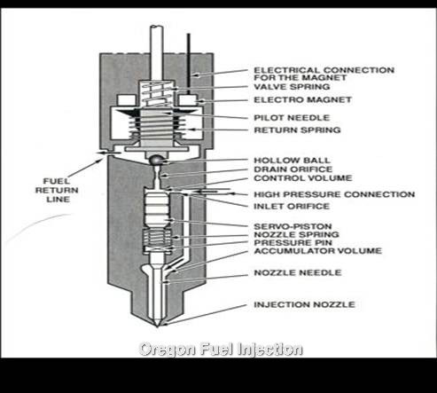
The high pressure pump builds rail pressure and delivers it to the fuel rail manifold where it flows through the injector lines to the injectors. The fuel pressure regulator in the high pressure pump controls rail pressure. The injectors have a hollow check ball that holds high pressure fuel until the fuel solenoid is actuated by the ECM, this allows the check ball to rise off its' seat and an injection to take place. If the check ball in the injector is leaking due to erosion on the seat or the high pressure limit valve leaks then it will not build enough rail pressure to start the engine. It takes approximately 2500 PSI rail pressure to start.
CAUTION
The fuel system contains high pressure fuel up to 26,000 PSI. Do not use you fingers to find fuel leaks! High pressure fuel entering your bloodstream may result in amputation or loss of life.
Check and record any DTC, look at snap shot data or save, do not erase codes prior to doing repairs, you will erase the snapshot and other relevant data
No Start or Hard Start
- Excessive fuel restriction, check or change fuel filter. Buy OEM Racor Replacement Fuel Filter
- Use a vacuum gauge to check the suction side of the fuel system. You should have no more than 5 inches Hg at WOT (wide open throttle) or 7-8 inches Hg under load. If you still have too much restriction after changing the filter, check for collapsing soft fuel lines by the drivers side valve cover and under the truck near the transmission. The fuel tank pick up may also be plugged. Too little vacuum (less than 2 inches Hg) means that it could be sucking air.
- Check for air in fuel system, install clears lines before and after the filter housing to check for air in the lines. Buy OEM Racor Fuel Filter Assembly
- Confirm actual versus desired rail pressure, even under crank no start conditions
- If the above are OK, then it comes down the following.
- fuel injectors (see injectors for more diagnostic information) Buy Bosch 6.6 LMM Injectors
- high pressure injection pump – CP3 pump. Buy Bosch Reman CP3 Pump
- Fuel pressure regulator, check to make sure it is not stuck. Buy Fuel Pressure Regulator
- fuel pressure relief valve (high pressure limit valve), check to make sure it is not leaking into the return system when rail pressure is 160 MPa. Buy 6.6 Relief Valve
- Before condemning the high pressure pump you need to make sure there are no high pressure fuel leaks.
Black Smoke
****Diagnosing smoke related issues on trucks equipped with diesel particulate filters may require temporarily disconnecting the filter or installing a test pipe to see the smoke.
- If at idle, use the scan tool to cut out one cylinder at a time and see if the smoke disappears.
- Dirty air filter
- Exhaust leaks or Boost leaks, you can usually hear a boost leak as a high pitched squeal under load.
- EGR and or MAF problems or intake leaks after the MAF sensor.
Misses
- Use scan tool to isolate one cylinder at a time. Run the injector balance test, running the test hot (after a hard drive) and in drive will give the most consistent results.
- A missing or damaged chamber gasket or low compression could cause a miss.
- Crankcase overfull (fuel dilution) can cause a rough run and balance rates out of specification.
Knock
- Use scan tool to isolate one cylinder at a time.
- Use cap off tools to block off one injector at a time.
- A slight knock can start occurring due to injector problems, often after a contaminated fuel problem.
Surge or Lope at idle
- Fuel pressure regulator: Map actual versus desired rail pressure, if the graph has a "shark tooth" pattern and there is no air in the system, it is usually caused by a bad fuel pressure regulator. Buy High Pressure Regulator
- Air in the fuel system (see fuel supply and filter housing section)
White – Blue smoke at idle when cold
****Diagnosing smoke related issues on trucks equipped with diesel particulate filters may require temporarily disconnecting the filter or installing a test pipe to see the smoke.
If the smoke clears in less than 1 minute, this could be normal depending on temperature and altitude. Blue white smoke that burns your eyes is un-burnt fuel; cold temperatures, high altitude and excessive idle time all mean cold combustion and white smoke.
- Possible bad injector, use the scan tool to cancel one cylinder at a time and see if the smoke clears up. However, using the scan tool to kill the injector does not reduce rail pressure in the injector and the tip can still leak fuel, cap off lines one at a time to pinpoint injector. Also look at the balance rates, if the tip is leaking fuel then the balance rates may be out of specification. Try increasing the rail pressure, we find injector nozzles that leak at idle pressure, but do not leak at higher pressure.
- Check glow plug operation when cold.
- Check rail pressure when engine is off, it should be 0 PSI
- Excessive idle time can cause white smoke when cold due to carbon build up on injector tips. More than 20% idle time is excessive. If the injectors have excessive carbon on the nozzle tip then balance rates should be high on that cylinder.
- An EGR cooler that is leaking internally can cause white coolant smoke, often after sitting overnight or for several hours during the day. Coolant smoke will smell sweet and not burn your eyes like fuel smoke.
Dilution
- Some dilution is normal for DPF equipped engines. Regeneration cycles will cause some fuel to leak past the piston rings in the cylinder and into the oil pan. Normal oil change intervals are critical for this reason.
- Leak at the high pressure pump drive shaft seal.
Fuel Supply and Fuel Filter Housing
The fuel filter housing is on the suction side (there is not a supply pump from the factory) and are prone to suck air. Follow the GM fuel system diagnosis in the service manual. Buy OEM Racor Fuel Filter Housing Assembly
- Install fuel vacuum test tool.
- Prime the fuel system with the hand primer until 10 PSI is indicated on the gauge, check for external leaks and repair. If the pressure drops from 10 PSI to 2 PSI in less than 1 minute, remove the fuel outlet line from the filter and cap it. Remove the ignition 1 relay and crank the engine for 2 – 15 second intervals, the high pressure pump should pull at least 12 inches of Hg vacuum. If air gets into the system it will cause a false/low reading.
- Install clear hoses at the inlet and outlet of the fuel filter housing. Re-prime the system and then start the engine, there should be very little air going into or coming out of the fuel filter housing.
- Common air ingestion places are the filter housing, drain valve, rubber hoses and quick connections. You need to use clear lines to isolate where the air is coming from and work your way back toward the tank until you don't have any more air coming through the clear line. Unless you know where to get the tool that sees through black rubber lines to find air, your only other option is to bounce around and replace parts.
- In some cases the "Filter Life Indicator" will be triggered prematurely, sometimes within 1000-5000 miles after changing the fuel filter. If this problem occurs even though the fuel filter is not restricted, it can be caused by excessive leakage on the high pressure side of the fuel system or other supply side issues. Verify there is no air in the supply system and restriction is not excessive under all load conditions. If these things check ok, diagnose the high pressure side as if there is low rail pressure codes. It seems that fuel flow is calculated in the ECM and is used to calculate fuel filter life. If the calculated flow is high, the ECM assumes a larger quantity of fuel has been filtered.
High Pressure Injection Pump (CP3 Pump) Buy Bosch CP3 Injection Pump
- Before condemning the pump for a starting issue you need to be certain that the rest of the high pressure fuel system is not leaking the pressure. Perform the injector return flow test.
- If there has been a major contamination issue with dirt and or water then it is very likely that the high pressure pump will need to be replaced. The injectors are typically damaged first, but any contamination that got into the injectors went through the CP3 pump first.
- The most common failure of the high pressure pump is the inability to keep up with high fuel demand such as towing a trailer up a hill. This problem will usually set a low rail pressure code.
- Other Notes:
- If the vehicle has starting issues then the injectors are the most likely cause. Perform the injector return flow test.
- If the vehicle only acts up during a hard pull with a load and there are no restriction issues then it is more likely a HP pump causing the problem. A bad limit valve could also cause this problem.
Injectors Buy Bosch LMM Fuel Injectors
It takes about 2500 PSI rail pressure for the injectors to deliver fuel and the engine to start.
- Injector return flow; maximum allowable leakage for one injector is 5 ml in 15 seconds, maximum per bank is 20 ml: check when cranking, with the FICM disabled, pressure should be 114 – 135 MPa during cranking. Specifications are for API rating of 40-44.
- Excessive leakage from the injectors usually results in a starting issue, which could occur hot or cold, but usually occurs hot because the fuel is thinner when hot. Excessive leakage from the injectors can also cause a DTC P0087 to set. When using the scan tool to increase rail pressure at idle, if you can't get to 21,000 PSI then the injectors are usually bad.
- You can also use balance rates to help determine if you have any bad injectors. If an injector is leaking excessively into the return the balance rates are often at the edge of specification. Injectors that have a poor cylinder power contribution or a noise or smoke change when canceled will also need to be replaced and are likely to cause low rail pressure during cranking.
- Enhanced Injector Return Flow Test- GM has come up with a test for use on the later Duramax engines. The test steps are listed below-
A. Engine at normal operating temperature, 181-189 deg. F.
B. Remove return hoses from one bank of injectors.
C. Use adapters to run hoses off of injector returns in to individual graduated containers.
D. Run engine until fuel flows from all four injector return hoses. Then with the engine at idle, command rail pressure to 17,400 PSI with the scan tool. Place the hoses in the graduated containers for 30 seconds.
E. Turn off ignition and record measurements.
F. Repeat above steps on the other bank of injectors.
G. Add up all recorded measurements to determine total injector return volume. If the return volume is less than 144 ml for all 8 injectors, refer to the high pressure pump test. If the return volume is greater than 72 ml per bank, replace any individual injector with return volume greater than 18 ml. - Other Injector Notes
- Balance Rates, when checked hot in park or neutral, should indicate bad injectors. Any injectors that are more than +4/-6.9 are a possible cause for rough run and will set codes (see DTC's)
- Miss, smoke or rough run usually indicate that the injectors are the cause. LMM engines with a DPF may not show any smoke, but frequent DPF regeneration events would suggest poor combustion.
- We have seen a couple of vehicles with no starting issues, but injector return is excessive at higher rail pressures which may cause the P0087 to set.
- There is a thirteen digit IQA code unique to each injector that must be programmed into the ECM with a scan tool after installation. The IQA code must be programmed to the cylinder number in which it was installed.
Turbo Buy LMM Turbo and Parts
- LMM turbos have a vane position sensor, check actual versus desired.
- Vane position sensor codes indicate sticky or stuck vanes, unison ring wear, VGT actuator failure, restricted oil supply, or a VGT position sensor failure. The design of these turbos is nearly identical to 6.0l Powerstroke turbos which are known for this type of failure. The turbos may free up at higher rpm due in part to additional oil pressure/volume to drive the vane actuator piston. Sticking unison rings are much more common than actuator or vane position sensor failures.
Diesel Particulate Filter
The diesel particulate filter traps soot from the exhaust to lower particulate emissions. During certain driving conditions the engine will perform a regeneration cycle, which will use additional fuel injections and the catalyst to heat up the exhaust temperatures to the point where the soot will be burnt out and form ash. Over time the DPF will become "ash loaded" and need replaced or cleaned.
Any engine drive-ability issues or fuel system failures will cause premature plugging or failure of the DPF. If the DPF is plugging repeatedly or requiring excessive regeneration cycles there is probably another problem with the engine, turbocharger, fuel system, or EGR system. Repair all other problems PRIOR to addressing the DPF issues.
- DO NOT reset the DPF timer unless the DPF has been replaced or cleaned (removed and cleaned, not regenerated in the vehicle). The ECM keeps track of fuel used, soot, and ash load. Excess soot and ash load will result if the timer is reset without replacing or cleaning the DPF.
- If the DPF has been deleted, customers will have run-ability issues if they do not have the correct software. We have also seen EGR related issues that do not set codes with delete software installed. These problems may cause heavy smoke and low power, as well as some other symptoms.
- A plugged DPF can cause a turbo failure by forcing exhaust under excess pressure around the turbine shaft seals. Low boost/low power complaints must be diagnosed properly and completely prior to repairs!
- Excessive idle time will also cause DPF restriction due to particulate build up at idle. This will cause poor mileage (zero MPG when idling) due to more frequent regeneration events. Excess idle time could be defined as leaving the pick up running while hooking up a trailer.
- Using Stanadyne Performance Formula fuel additive, which improves cetane, will reduce regeneration events and improve mileage around town. This is due to a better burn when cold and fewer particulates getting to the DPF.
Use the following information regarding diagnostic trouble codes in addition to the normal diagnostic procedures outlined in the service manual or technical service bulletins.
DTC Codes
P003A Turbo Boost Control Position Not Learned
- Usually sets in conjunction with a P2563 Turbo Boost Control Sensor Performance code. This code usually sets when the unison ring in the turbo is sticking.
- A defective VGT – Vane position sensor can also cause this code to set. The Vane position sensor can be removed and when the plunger is moved, it should register between 0-100% on the scan tool.
- Use a Tech2 scan tool to attempt VGT learn. If it will not learn, the unison ring is likely sticky or stuck.
- The vane position may not change at idle, when commanded, but does change sluggishly at higher RPM. This is usually caused by a sticking unison ring. Higher oil pressure and volume at higher rpm will force the unison ring to move. The turbo needs to be replaced.
- Also see P2563 below.
P0087 Fuel Rail Pressure Too Low
See Enhanced Injector Return Flow Test above also.
- Excessive restriction, fuel supply, plugged filter or sucking air. Install special tool J44638 to check vacuum restriction on fuel supply to the high pressure pump. Maximum restriction at WOT (wide open throttle) is 5 inches HG in park. When driving under hard acceleration maximum would be 7-8 inches Hg. If too high replace the fuel filter and retest.
- Check the fuel lines on the drivers side valve cover and between the transmission and frame for kinking.
- If restriction is only a couple of inches vacuum, that could indicate that the fuel supply system is sucking air, use clear fuel lines at the filter head to check for air.
- Rail pressure should read 1-1.8 MPa with key on and engine off. If out of range replace the rail pressure sensor.
- Check fuel return from the high pressure limit valve or fuel pressure relief valve. If it is leaking then it will need to be replaced. We have also heard of race plugs leaking, even if you have a race plug, you may want to check for leakage at max rail pressure.
- With the engine up to operating temperature, use the scan tool to command rail pressure to 21,000 PSI, if the rail pressure will not achieve 21,000 PSI at idle you most likely have a problem with the injectors, Especially if you are having a hard start, miss, rough run or smoke and balance rates are excessive. Perform the enhanced injector return test.
- Disconnect the fuel rail pressure sensor the fuel pressure should be greater than 175 MPa as displayed on the scan tool.
- If these codes set only on hard acceleration or when pulling a hill with a load, check fuel supply issues first. Then see if rail pressure will reach 21,000 PSI at idle, if it does then the low rail pressure under a heavy load is usually caused by a bad high pressure pump.
P0101 MAF Sensor Performance
- Most commonly sets due to an aftermarket air filter or intake kit/modifications.
- Check for ECM updates
- May cause the engine to go into a limp mode.
P0191 Fuel Rail Pressure Sensor Performance
- Most commonly caused by a defective rail pressure sensor or sensor pigtail
- Bad batteries or battery cable connections have been known to cause this code
P029D Injector 1 Leak, P02A1Injector 2 Leak, P02A5 Injector 3 Leak, P02A9 Injector 4 Leak, P02AD Injector 5 Leak, P02B1 Injector 6 Leak, P02B5 Injector 7 Leak, P02B9 Injector 8 Leak
- If an injector balance rate exceeds -7.0 these codes will set.
P0401 EGR Insufficient Flow
- Check for ECM updates
- EGR coolers commonly will plug up and cause this code to set.
- EGR valve failure may cause this code to set.
- Aftermarket air intake kits or filters can cause MAF related codes to set.
P0546 EGT Sensor 1 Circuit High Voltage
- See P2033, similar procedure, different sensor.
P0571 Cruise Control Brake Switch Circuit Malfunction
- Almost always sets due to a bad brake lamp switch but can also be a third brake light, fuse, or cruise control switch, among other possible causes.
- This code will keep the ECM from performing regeneration and will often lead to other DPF related codes (P1448, P244B, P2463)
P1448 DPF Regeneration Frequency Too Low
- If regeneration cycles are not completed as requested by the ECM, this code will set. Short drive cycles and other codes that may stop regeneration are the typical causes.
- Often sets in conjunction with P2463 and P244B.
P20E2 EGT Sensor 1-2 Correlation
- Sets in conjunction with P0546/P2033 or other EGT related codes
- Diagnose sensor codes first
P2033 EGT Sensor 2 Circuit High Voltage
- Sensor 2 is between the DOC and DPF
- Most commonly caused by a bad EGT 2 sensor, although it can also be a wiring issue.
- If the EGT reads 1800+ degrees KOEO, use a fused jumper wire to jump the two EGT sensor wires at the harness connector. The temp should read less than -40 degrees. If it does, replace the EGT sensor. If not, check wire harness and connector.
- This code will keep the DPF from regenerating.
P2146, P2149, P2152, P2155 Injector Positive Voltage Control Circuit Group 1-4
- Group 1–DTC P2146 with injectors 1 and 4
- Group 2–DTC P2149 with injectors 6 and 7
- Group 3–DTC P2152 with injectors 2 and 5
- Group 4–DTC P2155 with injectors 3 and 8
- Shorted injector solenoids or wire harnesses may cause these codes to set.
P244B DPF Differential Pressure Too High
- Perform service regeneration procedure
- Make sure there are no other engine or drive train codes that will keep the ECM from performing regular regeneration cycles.
P2463 DPF Soot Level Accumulation
- Perform service regeneration procedure
- Refer to GM TSB 10-06-05-002
- The DPF may need to be removed and cleaned or replaced
P2563 Turbo Boost Control Sensor Performance
- Commonly sets when the unison ring is sticking in the turbo. Usually sets in conjunction with a P003A Turbo Boost Control Position Not Learned code.
- A defective Vane position sensor can also cause this code to set.
Other Useful Tips
- Medium Duty GM trucks (C4500+) may have a rear axle steer switch located in the center of the dash. If this switch is turned on, the engine will have low power, low boost, and low rail pressure readings. This switch will also be in trucks without rear steer!
- Chassis Cab and Medium Duty trucks with a PTO will exhibit the same symptoms as listed above if the switch is on.
- Injector commanded pulse width can be used to determine injector/cylinder issues. As a general rule, anything under .30 ms at idle in gear will indicate an over fueling injector. Anything over .50 will indicate an under fueling injector or weak cylinder.
- Firing Order 1-2-7-8-4-5-6-3
2001-2007 6.6 L Duramax
PDF: 2001 – 2007 6.6 L Duramax
In order to do proper diagnostics you will need a scan tool and some special tools such as a vacuum test gauge J44638 (OTC 6754) available from GM Special Tools. Also note that 1 Mpa (megapascal) is equal to approximately 145 PSI.
If you don't have service information you can buy a subscription online at alldatadiy.com or eAutorepair.net.
High Pressure Common Rail Basic Information
The high pressure pump builds rail pressure and delivers it to the fuel rail manifold where it flows through the injector lines to the injectors. The fuel pressure regulator in the high pressure pump controls rail pressure. The injectors have a hollow check ball that holds high pressure fuel until the fuel solenoid is actuated by the ECM, this allows the check ball to rise off its' seat and an injection to take place. If the check ball in the injector is leaking due to erosion on the seat or the high pressure limit valve leaks then it will not build enough rail pressure to start the engine. It takes approximately 2500 PSI rail pressure to start.
CAUTION
The fuel system contains high pressure fuel up to 25,000 PSI. Do not use you fingers to find fuel leaks! High pressure fuel entering your bloodstream may result in amputation or loss of life.
Preliminary checks
- Check the oil level, LB7 engines have the injectors under the valve cover and are very susceptible to dilution.
- Check and record any DTC, look at snap shot data or save, do not erase codes prior to doing repairs, you will erase the snapshot data.
No Start or Hard Start
- Excessive fuel restriction, check or change fuel filter
- Use vacuum gauge, check the suction, you should have no more than 5 inches Hg at WOT (wide open throttle) or 7-8 inches Hg under load. If you have too much suction, after changing the fuel filter, the restriction could also be the sock in the tank. Too little vacuum (less than 2 inches Hg) means that it could be sucking air.
- Check for air in fuel system, install clears lines before and after the filter housing to check for air in the lines.
- Confirm actual versus desired rail pressure, even under crank no start conditions
- If the above check good, then it comes down the following.
a. fuel injectors (see injectors for more diagnostic information) Buy 6.6 Duramax Fuel Injectors
b. high pressure injection pump – CP3 Buy Bosch CP3 Injection Pump for Duramax
c. Fuel pressure regulator, check to make sure it is not stuck. Buy 6.6 Fuel Pressure Regulator
d. fuel pressure relief valve (high pressure limit valve), check to make sure it is not leaking into the return system when rail pressure is 160 MPa. Buy Duramax 6.6 Relief Valve - Before condemning the high pressure pump you need to make sure there are no high pressure fuel leaks. Use the EN-47589 (same block-off caps as #9011 SPX Miller tools) cap set to cap off the injector rail to isolate the injectors from the injector return system.
Black Smoke
- If at idle, use the scan tool to cut out one cylinder at a time and see if the smoke disappears.
- Dirty air filter
- Exhaust leaks or Boost leaks, you can usually hear a boost leak as a high pitched squeal under load.
- EGR and or MAF problems or intake leaks after the MAF sensor.
Misses
- Use scan tool to isolate one cylinder at a time. Run the injector balance test, running the test hot (after a hard drive) and in drive will give the most consistent results.
- A missing or damaged chamber gasket or low compression could cause a miss.
- Crankcase overfull (fuel dilution) can also cause a rough run and balance rates out of specification.
Knock
- Use scan tool to isolate one cylinder at a time.
- Use cap off tool EN-47589 to block off one injector at a time. A slight knock can start occurring due to injector problems, often after a contaminated fuel problem.
Surge or Lope at idle
- Fuel pressure regulator (FPR): Map actual versus desired rail pressure, if the graph is wavy and there is no air in the system it is usually caused by a bad fuel pressure regulator. Buy 6.6 High Pressure Regulator
- Air in the fuel system (see fuel supply and filter housing section)
White or Blue smoke at idle when cold
If the smoke clears in less than 1 minute, this would be normal depending on temperature and altitude. Blue white smoke that burns your eyes is un-burned fuel; cold temperatures, high altitude and excessive idle time all mean cold combustion and white smoke.
- Possible bad injector, use the scan tool to cancel one cylinder at a time and see if the smoke clears up. However, using the scan tool to kill the injector does not reduce rail pressure in the injector and the tip can still leak fuel, cap off lines one at a time (cap is tool # EN-47589) to pinpoint injector. Also look at the balance rates, if the tip is leaking fuel then the balance rates may be out of specification. Try increasing the rail pressure, we find injector nozzles that leak at idle pressure, but do not leak at higher pressure.
- Check glow plug operation when cold.
- Check rail pressure when engine is off, it should be 1.0-1.8 MPa(145-261 PSI) LB7 and LLY, or 0 PSI LBZ and LMM. Skewed rail pressure readings will usually not cause a hard start.
- Excessive idle time can cause white smoke when cold due to carbon build up on the injector tips. More than 20% idle time is excessive. If the injectors have excessive carbon on the nozzle tip then balance rates should be high on that cylinder.
- Some LLY engines have a reflash that addresses rough run, miss, and smoke concerns. Check to make sure the ECM is up to date.
Dilution
- Cracked injector
- Injector return lines are under the valve cover on LB7 engines. Pressurize the return circuit with the valve covers off and look for bubbles or vacuum test the return circuit off of each head, the return should hold 15 inches Hg of vacuum.
- LB7 dilution problems that occur after you have replaced the injectors could be return line leaks under the valve cover or leaks at the injector line to injector connection. Stripped allen head return banjo bolts may not torque or seal properly. Buy LB7 Injector Return Bolts
- We highly recommend vacuum testing the injector returns after replacing the injectors and before installing the valve covers to be sure there is no leaks. This can save a lot of labor in the long run and customer down time.
- The green coated injector lines are more susceptible to leaks versus the polished steel colored lines. Buy LB7 Injector Lines
- Leak at the high pressure pump drive shaft seal.
- You can also use a dye in the fuel and black light kit to try to pinpoint leaks at the injectors on an LB7. Follow the "fuel leaks inside of engine" GM service information.
Fuel Supply and Fuel Filter Housing
The fuel filter housing is on the suction side (there is not a supply pump from the factory) and are prone to suck air. Follow the GM fuel system diagnosis in the service manual. Buy Duramax Fuel Filter Housing
- Install fuel vacuum test tool.
- Prime the fuel system with the hand primer until 10 PSI is indicated on the gauge, check for external leaks and repair. If the pressure drops from 10 PSI to 2 PSI in less than 1 minute, remove the fuel outlet line from the filter and cap it. Remove the ignition 1 relay and crank the engine for 2 – 15 second intervals, the high pressure pump should pull at least 12 inches of Hg vacuum. If air gets into the system it will cause a false/low reading.
- Install clear hoses at the inlet and outlet of the fuel filter housing. Re-prime the system and then start the engine, there should be very little air going into or coming out of the fuel filter housing.
- Common air ingestion places are the filter housing, plugged filter, drain valve, rubber hoses and connections. You need to use clear lines to isolate where the air is coming from and work your way back toward the tank until you don't have any more air coming through the clear line. Unless you know where to get the tool that sees through black rubber lines to find air, your only other option is to bounce around and replace parts.
High Pressure Injection Pump (CP3 Pump) Buy Duramax High Pressure CP3 Pump
- Before condemning the pump for a starting issue you need to be certain that the high pressure fuel system is not leaking the pressure. Perform the injector return flow test.
- If there has been a major contamination issue with dirt and or water then it is very likely that the high pressure pump will need to be replaced. However, the injectors are typically damaged first, but any contamination that got into the injectors went through the CP3 pump first.
- The most common failure of the high pressure pump is the inability to keep up with high fuel demand such as towing a trailer up a hill. This problem will usually set a low rail pressure code.
- Other Notes:
• If the vehicle has starting issues then the injectors are the most likely cause. Perform the injector return flow test.
• If the vehicle only acts up during a hard pull with a load and there are no restriction issues then it is more likely a HP CP3 pump causing the problem. A limit valve could also cause this problem.
Injectors Buy Bosch Injectors For 6.6 Duramax
It takes about 2500 PSI rail pressure for the injectors to deliver fuel and the engine to start.
- Injector return flow; maximum allowable leakage for one injector is 5 ml in 15 seconds, maximum per bank is 20 ml: check when cranking, with the FICM disabled, pressure should be 114 – 135 MPa during cranking. Specifications are for API rating of 40-44.
- GM only provides a specification for return fuel when cranking for LB7 engines, however, we have done some testing on a good running LB7 and found that injector return flow at idle from one bank was 95 – 110 ml in one minute at 21,000 PSI.
- Excessive leakage from the injectors usually results in a starting issue, which could occur hot or cold, but usually occurs hot because the fuel is thinner when hot. However, excessive leakage from the injectors can also cause a DTC P0087, P0093 or a P1093 to set. When using the scan tool to increase rail pressure at idle, if you can't get to 21,000 PSI then the injectors are usually bad.
- You can also use balance rates to help determine if you have any bad injectors. If an injector is leaking excessively into the return the balance rates are often at the edge of specification. Injectors that have a poor cylinder power contribution or a noise or smoke change when canceled will also need to be replaced and are likely to cause low rail pressure during cranking.
- LBZ Enhanced Injector Return Flow Test- GM has come up with a test for use on the later Duramax engines. This test is specifically for the LBZ engine, but could be applied to LLY and LMM engines also. The test steps are listed below-
- Engine at normal operating temperature, 181-189 deg. F.
- Remove return hoses from one bank of injectors.
- Use adapters to run hoses off of injector returns in to individual graduated containers.
- Run engine until fuel flows from all four injector return hoses. Then with the engine at idle, command rail pressure to 17,400 psi with the scan tool. Place the hoses in the graduated containers for 30 seconds.
- Turn off ignition and record measurements.
- Repeat above steps on the other bank of injectors.
- Add up all recorded measurements to determine total injector return volume. If the return volume is less than 144 ml for all 8 injectors, refer to the high pressure pump test. If the return volume is greater than 72 ml per bank, replace any individual injector with return volume greater than 18 ml.
- Other Injector Notes
- Balance Rates, when checked hot in drive after a hard test drive, should indicate bad injectors. Any injectors that are more than +/- 6 are a possible cause for rough run.
- Miss, smoke or rough run usually indicate that the injectors are the cause. LMM engines with a DPF may not show any smoke, but frequent DPF regen events would suggest poor combustion.
- We have seen a couple of vehicles with no starting issues, but injector return is excessive at higher rail pressures, this can cause a P0093 or P1093.
- Some LLY engines have a reflash that addresses rough run, miss, and smoke concerns. Check to make sure the ECM is up to date.
Turbo Buy Turbos for Duramax Engines
- 2001-2006; turbo bearing failure may be caused by a spun camshaft bearing. Inspect for a spun number 4 camshaft bearing, refer to TSB 03-06-93-001B.
- 2004.5 and newer turbos have a vane position sensor, check actual versus desired.
- Vane position sensor codes a lot of times indicate sticky or stuck vanes, or unison ring wear. The design of these turbos is nearly identical to 6.0 Powerstroke turbos which are known for this type of failure. The turbos may free up at higher rpm due in part to additional oil pressure/volume to drive the vane actuator.
Use the following information regarding diagnostic trouble codes in addition to the normal diagnostic procedures outlined in the service manual or technical service bulletins.
DTC Codes
P003A Turbo Boost Control Position Not Learned – applies to 04.5-07 with VGT turbo
- Usually sets in conjunction with a P2563 Turbo Boost Control Sensor Performance code. This code usually sets when the unison ring in the turbo is sticking.
- A defective VGT – Vane position sensor can also cause this code to set. The Vane position sensor can be removed and when the plunger is moved, it should register between 0-100% on the scan tool.
- Use a Tech2 scan tool to attempt VGT learn. If it will not learn, the unison ring is likely sticky or stuck.
- The vane position may not change at idle, when commanded, but does change sluggishly at higher rpms, this is usually caused by a sticking unison ring. Higher oil pressure and volume at higher rpm will force the unison ring to move, the turbo needs to be replaced. Buy Garrett Turbo for 6.6 Duramax
P0087; fuel rail pressure is less than 22.5 MPa at more than 600 RPM, fuel rail pressure too low. For LLY, LBZ, LMM, see Enhanced Injector Return Flow Test above also.
- Excessive restriction, fuel supply, plugged filter or sucking air. Install special tool J44638 to check vacuum restriction on fuel supply to the high pressure pump. Maximum restriction at WOT (wide open throttle) is 5 inches HG in park. When driving under hard acceleration maximum would be 7-8 inches Hg. If too high replace the fuel filter and retest.
- If restriction is only a couple of inches vacuum, that could indicate that the fuel supply system is sucking air, use clear fuel lines at the filter head to check for air. Buy Racor Fuel Filter Head Assembly
- Excessive restriction could also cause a DTC P1093 to set at the same time.
- Rail pressure should read 1-1.8 MPa with key on and engine off. If out of range replace the rail pressure sensor. (0 PSI LBZ)
- Check fuel return from the high pressure limit valve or fuel pressure relief valve. If it is leaking then it will need to be replaced. We have also heard of race plugs leaking, even if you have a race plug, you may want to check for leakage at max rail pressure. Buy 6.6 High Pressure Relief Valve
- With the engine up to operating temperature, use the scan tool to command rail pressure to 21,000 PSI, if the rail pressure will not achieve 21,000 PSI at idle you most likely have a problem with the injectors, especially if you are having a hard start, miss, rough run or smoke and balance rates are excessive. Perform the enhanced injector return test.
- Disconnect the fuel rail pressure sensor the fuel pressure should be greater than 175 MPa as displayed on the scan tool. Buy Duramax Fuel Rail Pressure Sensor
- If these codes set only on hard acceleration or when pulling a hill with a load, check fuel supply issues first. Then see if rail pressure will reach 21,000 PSI at idle, if it does then the low rail pressure under a heavy load is usually caused by a bad high pressure pump.
P0089; The engine control module (ECM) uses commanded fuel pump flow to determine a desired fuel rail pressure (FRP). The actual fuel pressure is monitored using the FRP sensor. If the FRP sensor indicates a pressure more than 20 MPa greater than desired, DTC P0089 will set.
- Open or poor connections at the MPROP (FPR) connector-pigtail or main engine harness connector will cause loss of pressure control, maximum rail pressure at idle.
- A stuck MPROP (FPR) can cause excessive rail pressure.
- Bad suction valves in the high pressure pump can cause rail pressure to be excessive.
- The ECM can fail and cause the rail pressure to increase beyond the desired amount.
P0093 on 2001 (P1093 on later vehicles); Difference between commanded fuel pressure and actual pressure is greater than 20 MPa.
- If P0087 is set solve P0087 first
- Similar diagnostics to DTC P0087
P0201 – P0208 misfire codes
- Can be caused by the FICM wire harness rubbing on the back of the alternator, alternator bracket or FICM harness retaining bracket.
- Air in the fuel system can also cause misfire codes.
P1093 Large Leak; difference between commanded fuel pressure and actual pressure is greater than 20 Mpa. Large leak means there is a leak in the high pressure system. Large leaks go into the return system and flow back to the tank, these are not external leaks.
- If P0087 is set, solve P0087 first.
- Similar Diagnostics to P0087
P2146 or 2149; cylinder bank shut down
- Can be caused by the FICM wire harness rubbing on the back of the alternator, alternator bracket or FICM harness retaining bracket.
- LLY engine (2004.5-2005), #2 (P0202) and #7 (P0207) misfire codes set with codes P2146 and P2149. Refer to TSB 05-06-04-047B to repair the injector harness brackets and connectors (part # 98017958) for #2 and #7 before replacing the FICM or the injectors. Buy #2, #7 Update for LLY, Buy 6.6 Duramax FICM
P2563 Turbo Boost Control Sensor Performance – applies to 04.5-07 with VGT turbo
- Commonly sets when the unison ring is sticking in the turbo. Usually sets in conjunction with a P003A Turbo Boost Control Position Not Learned code.
- A defective Vane position sensor can also cause this code to set.
Other Useful Tips
- Medium Duty GM trucks (C4500+) may have a rear axle steer switch located in the center of the dash. If this switch is turned on, the engine will have low power, low boost, and low rail pressure readings. This switch will also be in trucks without rear steering!
- Chassis Cab and Medium Duty trucks with a PTO will exhibit the same symptoms as listed above if the switch is on.
- Injector commanded pulse width can be used to determine injector/cylinder issues. As a general rule, anything under .30 ms at idle in gear will indicate an over fueling injector. Anything over .50 will indicate an under fueling injector or weak cylinder.
- Firing Order 1-2-7-8-4-5-6-3
6.5 L DS Pump Diagnostics
PDF: 6.5 L DS Pump Diagnostics
To properly diagnose a 6.5L vehicle with the DS model pump you will need a scan tool. The 1994 and 1995 are OBD1 and the 1996 through the 2000 model year is OBD2, so the diagnostic codes are different depending on the year range.
If you don't have service information you can buy a subscription online at alldatadiy.com or eAutorepair.net.
Do Not use the starter to turn the engine over when the injection pump is removed or when turning the engine to torque/remove the injection pump drive bolts. The gear can bind up and cause the crankshaft key to shear off.
LOW POWER
- Low or no fuel supply pump pressure
- Dirty fuel filter
- Wastegate control solenoid (low boost). Buy 6.5 Wastegate Controls
WHITE SMOKE
- Low or no fuel supply pump pressure
- Retarded timing, use Tech 2 scan tool to perform TDC offset learn procedure. We normally set the timing to -1 to -1.5 degrees.
- Low engine compression, cracked pistons.
BLACK SMOKE
- Dirty air filter
- Waste gate control solenoid failure, or low vacuum. Buy GM 6.5 Wastegate Control Solenoid
- Worn injectors (excess carbon on the nozzle tips) Buy 6.5 Diesel Injectors
- Low or no fuel supply pump pressure
- If this occurred after the plenum chamber (intake) was removed, check the EGR tower gasket, if not seated EGR gases enter the intake unrestricted and in excessive quantity.
- Restricted exhaust system, if the vehicle has been "babied", the cat will partially plug. Take the vehicle out for several full throttle accelerations to clear out the exhaust
HARD START HOT
- If the complaint is a hard start after a hot soak, not a stalling condition then hard start, check for a minimum cranking speed hot of 200 rpm.
MISS
- Worn injectors. Buy Chevy 6.5 Diesel Injectors
- If the engine was overheated, check for a head gasket problem, usually on the turbo side (usually #4 & #6).
- See Misfire Codes further below.
- Low engine compression, cracked pistons.
NO START, DIES INTERMITTENTLY OR STALLING
This is often caused by a bad PMD (Pump Mounted Driver or Fuel Control Solenoid Driver); however it is unusual to have multiple failures of the PMD. A bad Fuel control Solenoid (part of the injection pump) can cause the same symptoms and codes. A bad EGR, EGR vent, wastegate control, and transmission solenoid are on the same quad driver circuit and can cause intermittent stalling.
PMD (Pump Mounted Driver) Buy PMD for GM 6.5 Diesel, or Buy a DS4 Injection Pump for 6.5
The pump mounted driver gets fused 12 volt power when the key is on.
The PCM then sends a signal to the PMD to close the fuel control solenoid. When the fuel control solenoid closes it sends a signal back to the PMD and that is relayed to the PCM. The response time of the closure signal is called C-time.
C-Time should change slightly when the engine is accelerated or decelerated. A fixed C-Time can indicate a bad Fuel Control Solenoid, which is in the pump. If the C-Time is erratic when the RPM is stable then this usually indicates a bad PMD. See Wire Harness Testing for other possible problems. See PMD replacement guideline below.
PMD REPLACEMENT GUIDELINE
Prior to replacement of the PMD we use the following guidelines to determine if a PMD may need to be replaced. This is a simple first step and is less in depth than the GM bulletin noted below. Also be aware that the PMD is powered by a quad driver circuit in the PCM. This circuit also powers the EGR vent solenoid, EGR control solenoid, wastegate control solenoid and the 1-2 shift solenoid. If any of these solenoids have an intermittent short the thermal protected quad driver circuit will trip and shut down all 4 circuits, which can cause intermittent stalling, then reset and run again.
Check for system voltage between the pink and black (ground) wires at the wire harness connection to the PMD and Fuel Control solenoid (4 wires), it should be battery voltage. Fix low voltage issues as well as any other problems such as no fuel supply pump pressure before replacing the PMD.
Replace the PMD if;
- If the complaint is "intermittent dies with no codes" and you can't duplicate it. remember that a bad noise suppression harness can cause intermittent stalling.
- Intermittent dies with no closure errors (closure errors are usually caused by the fuel control solenoid).
- Intermittent stalling and C-Time varies, as normal, during acceleration and deceleration (if C-Time is "stuck" at 1.95ms or 2.25ms this usually means a bad fuel control solenoid).
- If you have a no start and C-Time is 1.95ms (94-95) or 0.01ms (96-2000) replace the PMD
- C-Time is erratic at idle while idle rpm is stable.
- Buy PMD for GM 6.5 EFI Diesel Engine
Note:
- Normal C-Time is between 1.5ms – 1.9ms. C-Time readings that are too high, but stable, are usually a result of a bad fuel control solenoid inside the injection pump not a PMD.
- If the PMD is missing the heat transfer pad, it can overheat and cause intermittent stalling.
- If the PMD is not mounted to a heat sink, either the pump housing or a finned remote mount, it can overheat and cause intermittent stalling.
*If the problem you are experiencing doesn't correspond with the problems noted above then follow the trouble shooting below to help pinpoint a possible bad PMD.
GM Bulletin #77-63-06A – follow these instructions if PMD replacement guidelines do not apply.
- Check fuel system for air (check at fuel return from pump), supply pump pressure, and fuel filter condition.
- Check the PCM and injection pump wiring harness for chaffing and/or loose terminals at the PCM connector, the 15 pin connector and the PMD connector. See the WIRE HARNESS CONNECTIONS section for more information.
- Check all engine and vehicle harness grounds.
- Check for loss of ignition voltage on terminal "D" at the PMD connection to the injection pump. Refer to ENGINE CONTROLS IN THE 1998 SERVICE MANUAL FOR ALL MODEL YEARS.
- Verify that the condition is still present:
– If the condition is no longer present, the vehicle is repaired
– If the condition is still present, and there are active DTC's set, go to step 6.
– If the condition is still present, and there are NO active DTC's set, go to step7. - For active DTC's 35 or P1216, refer to Engine Controls in the 1998 Service Manual for all model years. If the DTC diagnostic table flow chart directs you to replace the injection pump, replace the PMD (Pump Mounted Driver) which is also called the Fuel Solenoid Driver. Go to step 9.
- For stall condition, disconnect the Optical Sensor (Encoder Sensor) and operate the engine in back up mode (you will experience an extended crank time during starting, up to 15 seconds). A bad noise suppression harness or no noise suppression harness can also cause a stalling condition. If the condition is still present replace the PMD only. Go to step 9.
- For a no start condition, check injection pulse width (94-95) or C-Time (96-2000 Fuel Solenoid Closure Time) with a scan tool, while cranking (maintain minimum cranking speed 100 rpm cold and 200 rpm hot). If C-Time is 1.95ms (94-95) or 0.01ms (96-2000) replace the PMD. Go to step 9.
- Replacing the PMD:
The PMD must be mounted to a "heat sink" of some kind. Stanadyne (Injection Pump Manufacture) states that the PMD must be mounted to the injection pump with the heat pad underneath it. In order to mount the PMD to the injection pump you must remove the intake manifold. If you don't want to remove the intake manifold, you could purchase a remote mount kit such as the BD remote mount kit, and an aftermarket PMD. This would allow you to replace the PMD without removing the intake manifold.
Stanadyne has finally come out with a new PMD it is completely redesigned from the original PMD. Since the wire harness connections are different as well as the calibration resistor, the intake manifold must be removed in order to replace the PMD, because the wire harness between the PMD and the Fuel Control Solenoid will have to be replaced.
Removing the PMD requires a T15 TORX bit. Replace the heat transfer pad and use snap ring pliers to remove the calibration resistor. Install the calibration resistor into the new PMD.
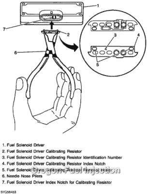
IMPORTANT: IF THE FUEL SOLENOID DRIVER CALIBRATING RESISTOR IS MISSING, DTC 56 (1994 1995) OR P1218 (1996-1998) WILL SET.
INSTALL FUEL SOLENOID DRIVER: Align the mounting screws on the PMD with the holes on the injection pump (or on the remote mount PMD heat sink) Torque the mounting screws to 23 LB-IN.
IMPORTANT: DO NOT INSTALL THE FUEL SOLENOID DRIVER WITHOUT A NEW HEAT TRANSFER PAD. DO NOT REUSE A HEAT TRANSFER PAD. USE A NEW HEAT TRANSFER PAD ONLY. THE HEAT TRANSFER PAD IS REQUIRED TO PREVENT RAPID FAILURE OF THE FUEL SOLENOID DRIVER FROM OVERHEATING.
NOTICE: DO NOT OVER TIGHTEN FUEL SOLENOID DRIVER MOUNTING SCREWS. DAMAGE TO THE FUEL SOLENOID DRIVER WILL RESULT.
For Other Starting Issues, Check the high resolution signal, cam signal (from the injection pump) and crank signal.
| High Res. Signal | x | 0 | x | x | x |
| Cam signal | x | x | 0 | x | 0 |
| Crank signal | 0 | x | x | 0 | x |
| Will it start? | Yes, extended crank | Yes | Yes | No | Yes, noisy on startup |
X = good signal, 0 = no signal
Hertz Readings (HZ) while cranking and at idle
| RPM | 140 | 160 | 180 | 200 | 700 | 800 |
| High Res. Signal | 597 Hz | 683 Hz | 768 Hz | 853 Hz | 2987 Hz | 3413 Hz |
| Cam signal and crank signal | 9 Hz | 11 Hz | 12 Hz | 13 Hz | 47 Hz | 53 Hz |
EGR
- Light duty engines utilize an EGR system to help meet emissions. The EGR flow calculation on some models uses the MAF sensor. If there are any "air intake leaks" either MAF or EGR codes can set. A missing or improperly sealing EGR tower gasket can cause either or both codes to set.
- Low or no vacuum from the vacuum pump can also cause EGR codes to set. A missing EGR tower gasket can cause a MAF low code to set, along with excessive black smoke, because it is pulling exhaust gases instead of clean air through the air filter.
- Failure to remove the block off plates from the intake manifold gaskets for a light duty engine can cause EGR codes because there will be no exhaust gases getting to the EGR valve.
FUEL SUPPLY PUMP
- The supply pump operates during cranking and after the engine oil pressure comes up. The supply pump is driven from a relay on the firewall or in the under hood fuse-relay center. The oil pressure sensor also includes a switch to operate the supply pump once oil pressure comes up after starting. Buy 6.5 Fuel Supply Pumps and Oil Pressure Switch
- The supply pressure should be between 5-7 psi at idle. Test at the fuel filter drain at the front of the engine near the coolant crossover. Be aware that this is a test on the dirty side of the filter and if the filter is dirty the actual supply pressure to the injection pump will be lower.
- If the fuel supply pressure is zero, remove the fuel supply pump relay and jump #30 & #80 connector, this will send power to the supply pump with the ignition on. If you have good supply pressure now, then the most likely cause is a bad oil pressure sending switch. Buy 6.5 Oil Pressure Switch
- Low supply pressure can cause DTC P0370 (17) and P0251 (18) to set due to aeration in the fuel, after all it is an optical sensor and it can't see through an aerated mix.
MISFIRE CODES
- Misfire codes are handled differently for different years. Some misfire codes go by firing number order, in other words a misfire code for #2 would be #8 cylinder because it is the #2 cylinder in firing order. Check the service manual for the year you are working on.
Firing order is:
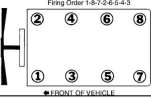
INJECTORS
The injectors on the 6.5 L are usually only good for about 100,000 miles. They get a lot of carbon blown up inside of the nozzle tip. This results in poor atomization and poor spray patterns. Buy 6.5 L Injectors and Install Kit
ENCODER SENSOR
If you have a no start condition, disconnect the encoder (optical) sensor and crank the engine for 15-20 seconds. If it starts then the problem is with the optical sensor.
The encoder sensor has to be able to see through the fuel inside the pump, if there is any air in the fuel it can cause trouble codes to set. Dirty fuel, SVO, no fuel supply pressure (air in system) or dyed fuel can all cause a problem with the encoder sensor "reading" the windows in the cam disk. There are 8 windows in the low resolution circuit and 512 windows in the high resolution circuit. In on minute at idle the high resolution circuit needs to read about 180,000 windows, in order to not set a code.
Replacing the encoder sensor requires at least partial disassembly of the injection pump, and once replaced it should be calibrated to the injection pump. For these reasons we do not recommend replacing just the encoder sensor.
TDC OFFSET LEARN
The pump to engine timing must be set with a scan tool. You need to do the TDC offset learn procedure in order to set base pump to engine timing.
TURBO Buy GM 6.5 Turbochargers
The turbo on the 6.5L EFI engine has a wastegate actuator that is controlled by vacuum. The wastegate actuator on the 94-2000 turbo does not have a spring, when no vacuum is applied the wastegate will "flop" back and forth. If the wastegate actuator holds a vacuum and it moves freely back and forth, when no vacuum is applied, then there is nothing wrong with the wastegate actuator. A turbo boost problem and DTC P0236 (78) is normally caused by low vacuum (need 20 inches HG) or a bad wastegate control solenoid.
To inspect the turbo, remove the inlet hose from the compressor inlet and make sure the turbo spins freely and that the compressor wheel does not rub on the housing when pushed to the side. Some side play is normal, because the bearings "float" on oil when the oil pressure comes up after starting.
The turbo pulls crankcase fumes through the CDR valve. It is normal for the turbo to discharge oil from the compressor housing. You have to determine if you have more oil coming out versus going into the compressor housing. A plugged air filter or bad CDR valve can cause excessive oil to be pulled out of the engine and discharged from the turbo back into the intake. If the silicone hose connecting the compressor discharge is not sealed with a minor amount of silicone sealant than the hose connection will weep oil past the hose.
WASTEGATE CONTROL SOLENOID
The wastegate (WG) control solenoid controls the amount of vacuum going to the wastegate actuator on the turbo. The WG solenoid is controlled via a pulse width modulated signal from the PCM. Buy 6.5 Turbo Waste Gate Controls
WIRE HARNESS TESTING
Poor electrical connections or wiring can cause most intermittent problems. Perform a careful check of the suspected circuit for the following:
Inspect and ensure the integrity of all related wiring harness connectors. If the wiring harness connectors are not properly put together or engaged before they are locked together, numerous types of conditions may occur. This may include many intermittent symptoms and DTC codes.
The first step in any type of electrical diagnosis is that a visual and physical inspection be completed of the wiring harness connectors for integrity. Many times, the vehicle may be repaired just by disconnecting and reconnecting the connectors. As with all repairs to wiring harness connectors and terminals, a pin test of the terminals within the connector should be performed. A pin test is performed by inserting the proper size terminal test tool (not a paper clip), into the terminal to determine whether or not the terminal is making good contact, or whether it has been damaged from prior improper connection, multiple connections or lack of connection.
COMMON DTC CODES
Note; multiple codes can set for just one fault, as if the other codes wanted to come to the party. On an OBD2 system use the Tech 2 scan tool to determine which code set first and under what condition, A DTC P0370 (17) can trip a DTC P0251 (18), a DTC P0251 can trip a P0335 (19) and a DTC P0335 can trip a DTC P1216 (35) or DTC P1217 (36)
DTC P0216 (34) injection pump timing control circuit
- Watch the stepper motor and make sure it retracts when activating TDC learn with a scan tool. If the stepper is not operating properly this code will set.
- This code will set if injection pump timing has not been set correctly.
- It will also set sometimes if the crank sensor is faulty.
- If the stepper motor shaft was bumped hard during handling while the pump was off, that can cause the stepper motor to bind and quit working.
DTC P0236 (78) turbo boost performance
- This code is usually caused by a bad wastegate control solenoid or low system vacuum. Buy 6.5 Turbo Waste Gate Solenoid
- Check vacuum at the wastegate actuator connection on the turbo. It should be 15" at idle. If it is not and vacuum at the inlet to the wastegate solenoid is at least 24", then the solenoid is bad. If the vacuum pump is not producing 24" of vacuum, then there are either leaks or the pump itself is bad. Buy Vacuum Pump for 6.5
DTC P0251 (18) injection pump cam sensor circuit (optical sensor)
- Similar to P0370 (see comments under DTC P0370), sets when cam reference counts are missed. Can also be set by contaminated fuel or aerated fuel like P0370.
- Bad connections in the harness connectors and or a bad noise suppression harness are common causes for this code.
DTC P0335 (19) crankshaft position reference error
- Bad crank sensor or wiring issue.
DTCP0370 (17) timing reference high resolution system performance – optical sensor
The optical sensor (encoder, cam) is used by the injection pump to determine injection timing relative to engine position. This code and the P0251 set when counts are missed from the pump cam but picked up from the engine crank position sensor. The optical sensor can not be changed with the pump on the engine. The pump has to be partially disassembled parts replaced and then tested on the test stand.
- Can be caused by aeration in the fuel from a plugged fuel filter, low fuel supply pump pressure, or low fuel level in fuel tank.
- Contaminated fuel or fuel with dyes in it. Red off road fuel or automatic transmission fluid in fuel can also cause the optical sensor to miss counts.
- Bad connections in the harness connectors and/or a bad noise suppression harness are common causes for this code.
DTC P1216 (35) fuel solenoid response time too short
- Sets if closure time is less than 1.2 ms or less than .75ms on later years.
- Commonly caused by bad PMD. Check the PMD harness circuits for good voltage and grounds prior to replacing the PMD. See "PMD Replacement" above.
- On some occasions this code can be set by a bad fuel solenoid in the injection pump.
DTC P1217 (36) fuel solenoid response time too long
- Closure time more that 2.5 ms.
- Can be caused by a weak fuel control solenoid, bad PMD, poor grounds, low supply voltage at PMD. See "PMD Replacement" above.
DTC P1218 (56) Injection pump calibration resistor error
- Usually is caused by a missing calibration resistor, and this code sometimes will only set after attempting TDC offset learn. Buy DS4 Calibration Resistor for 6.5
DTC P1125 (84) Accelerator Pedal Position Sensor System Performance
- This code can set if your foot is on the throttle and brake when key is turned on.
DTC P1214 (88) injection pump timing offset error
- The pump to engine timing must be set within +2.02 to -2.02 degrees when doing TDC offset learn or this code will set. You must reset timing (rotate the pump), clear the code and retry TDC offset learn.
- This code could also set if the starter was used to crank the engine over while installing the injection pump, this will sometimes partially shear the crankshaft timing chain gear key.
GM/Ford IDI Diagnostics Stanadyne DB2 Mechanical Pump
PDF: GM/Ford IDI Diagnostics Stanadyne DB2 Mechanical Pump
Hard Start/No Start Cold – White Smoke
- The fact there is smoke indicates that there is fuel in the cylinders, so it is likely a cylinder heat, compression, or timing issue.
- Check glow plug operation- Verify there is voltage at the relay terminals and glow plug terminals when the key is cycled to the on position and the glow plug lamp is illuminated. If not, the relay and/or controller are likely bad. Glow plug cycle time should be around 8-10 seconds for the pick-ups/vans/Blazer/Suburban, up to 15 seconds for GM CUCV military vehicles. Buy 6.2 and 6.5 Glow Plug System Parts
- If there is voltage, ohm the glow plugs with the wires disconnected. The ohm readings should be between .4-.8 ohms typically. If the reading is high or open, the glow plug is bad. Open or high resistance can cause short cycle times with the later Ford solid state controllers.
- If the glow plugs are operating normally: Low engine compression, incorrect injection pump to engine timing, poor quality/incorrect fuel will all also cause a hard start cold with white smoke.
- Verify that cranking speed is at least 100 RPM.
Hard Start, Cold or Hot – No Smoke
- The lack of smoke generally means no or insufficient fuel is entering the cylinder.
- Verify that cranking speed is at least 180-200 RPM if engine is hot, minimum 100 rpm cold.
- Check for 12 volts at the shut off solenoid connection on the injection pump with the key on. Also listen for a "click" when power is applied.
- Verify that there is a good, clean, and not aerated fuel supply at the injection pump. Tee in a gauge and clear line at the pump inlet or as close as possible to the pump inlet to get a pressure reading and visually check for air bubbles. Fuel supply pressure should be roughly 4-8 PSI for most all DB2 model pumps.
- If the pump was just installed and not properly bled there could be an airlock. Loosen one injection line and plug in/unplug the shutoff solenoid a few times until you get fuel out the line then tighten that line and go to the next injection and repeat to be sure there is not an airlock.
- Loosen several injection lines at the injector end and crank the engine. If there is good fuel supply to the pump and no fuel being delivered within 30 seconds total of cranking, then the pump is likely defective.
Surges while Running
- Surging can be caused by either fuel supply problems or mechanical problems within the injection pump itself.
- Check for air in the fuel supply system. Check for air at the bleeder valve on the filter head. If air comes out when the bleeder is opened there is air in the system.
- To find the source of the air, install a clear line at the suction side of the supply pump and start the engine. If there is air in the fuel, move the clear line to the next available location in the supply line from the fuel tank, such as a primary filter, hose connection at a tank switch valve, ETC. When you stop seeing air in the fuel, then the component you have isolated is at fault. Common items that suck air are old fuel lines, bad o-rings in quick connect fittings, tank switch valves, primary fuel filters (especially early 6.9l Fords), and fuel supply pumps.
- If there is no air in the fuel supply and the engine is surging, it is very likely that there are worn or sticking governor components in the injection pump. Buy 6.2 and 6.5 Mechanical Injection Pumps
- If the cold advance solenoid is stuck on with constant power due to a bad cold start switch, the engine may surge. Buy 6.2, 6.5 Cold Start Sender Switch
Starts and Then Dies
- A start and die issue is normally caused by a drain back issue in the fuel supply system or low idle speed. If the engine started right away it is typically not a glow plug issue.
- If the engine runs for less than 1 or 2 seconds, dies, and restarts immediately then the problem is usually too low of an idle speed, no cold start fast idle, or incorrect timing.
- If the engine runs for ½ -10 seconds then dies and is difficult to re-start, it is most likely a drain back issue. External fuel leaks can indicate a problem area. Check the injection pump throttle shaft, advance plunger seal, injector returns and fuel supply lines. If you are seeing damp areas, but no visible fuel, this could still cause the drain back issue because air can get in where fuel can't get out. The fuel filter check valve on 7.3L engines is also known problem area for this complaint. The longer the engine runs before it dies, the further back toward the tank the problem is.
- If the return fitting on the injection pump is plugged or the return to the tank is restricted it will also cause a start then die issue.
Dies on Deceleration
- This is a common problem with low lubricity fuels, which cause slow response from the metering valve in the injection pump or when a vehicle has been sitting unused for some time.
- If the engine dies when the operator lets off of the throttle but the engine easily restarts, it is possible that the idle RPM are just set a little too low. It could also be low lubricity fuel. Try using Stanadyne Performance formula fuel additive; this will often solve a "dies on deceleration" problem after just a short drive. Buy Stanadyne Performance Formula
- If the engine dies and then is slow to restart, the problem could be a sticking metering valve in the injection pump. Low lubricity fuels, old gummy fuel, or water contamination can lead to this problem. Check the fuel filter for signs of water or other contamination which would indicate a likely pump failure. Use a lubricity additive, such as Stanadyne Performance Formula, and see if the problem clears up. If not, the injection pump may need replaced.
White Smoke (may also be blue/white)
- White smoke with a fuel smell is caused by incomplete combustion in the cylinder. Unburned fuel smoke will burn your eyes.
- Verify pump to engine timing: Use a timing meter or timing light with a diesel adapter to verify dynamic injection pump timing. Retarded timing or timing that is too far out of range either way will cause white smoke. IF the smoke is mainly when the engine is cold, make sure the cold advance solenoid in the injection pump is receiving power until the engine reaches approximately 120 degrees coolant temperature.
- Make sure the fuel supply is clean, not aerated, and the correct fuel. Old poor quality fuel or a gas/diesel mix will cause white smoke due to incomplete/incorrect combustion.
- Coolant or oil in the combustion chamber can cause white smoke, but this smoke usually smells sweet (coolant) or oily (oil). If it is oil smoke; how many miles per quart of oil burned?
- Low engine compression will cause white smoke.
- An injector with a leaking or stuck nozzle may cause white smoke and is usually accompanied by a fuel knock. Crack open fuel lines to see if knock goes away. Buy Chevy 6.2 Diesel Injectors
- A worn injection pump can cause white smoke at all times. Buy 6.2 Rebuilt Injection Pump
Black Smoke
- Black smoke is caused by excessive fuel or a lack of air flow (or both) into the cylinder, causing a fuel "rich" condition. It should also be noted that some light black smoke at high RPM, under load, and/or at higher altitudes is typical of a naturally aspirated IDI diesel engine.
- Check the air filter. This is often overlooked and is a simple fix.
- Verify pump to engine timing. Over advanced timing can contribute to black smoke.
- If the engine is turbo charged, after market or OEM, verify boost pressure is within specification (usually 8-12 PSI). If not, look for exhaust leaks pre-turbo, exhaust restriction post-turbo, air inlet restriction, or boost leaks.
- Worn injectors may cause black smoke due to poor spray patterns, leaking tips, and/or incorrect timing (low opening pressures). Buy 6.2 Replacement Injectors
- A worn injection pump can cause black smoke due to worn advance components, worn governing parts, and/or incorrect calibration. Buy Chevy 6.2 Injector Pump
- If the engine is equipped with EGR (some 6.2l and 6.5l engines), the system can malfunction and cause black smoke and low power.
- Aerated fuel may cause black smoke with out surging or dying (usually on the 7.3L).
Miss, Rough Run
- A miss that can be isolated to one cylinder is probably not an injection pump issue, more commonly it will be an injector or base engine problem. A miss that can not be isolated to one cylinder is most likely an injection pump related problem or engine balance issue (dual mass flywheel, balancer, ETC.).
- Try to isolate the problem to one cylinder by cracking the injection lines one at a time while the engine is running and listening for a change in the engine. If there is no or very little change, that is the problem cylinder. Check all components related to that cylinder specifically, such as the injector, valve train, and compression.
- If the problem can not be isolated, check the flywheel (manual transmission), flex plate (auto transmission), vibration dampener (balancer), fan clutch, ETC. for any signs of failure or excessive play.
- Check idle speed: Too low of an idle speed can make the engine feel like it is running rough, especially when the transmission is in gear or the engine is loaded at idle (A/C compressor).
- If no other problems are found, it is likely an injection pump problem. Buy Chevy 6.2 DB2 Injector Pump
Low Power
- Make sure the injection pump is getting full throttle travel. Worn linkages, cables, and levers can limit throttle travel.
- Check pump to engine timing.
- If turbocharged, see "Black Smoke"
- Verify a good fuel supply to the injection pump, 4-6 PSI supply pressure with no aeration.
- Check/test the injectors. Low opening pressures, poor spray patterns, and worn nozzles will contribute to low power. Buy 6.2 Injectors
- Determine the condition of the injection pump by measuring return fuel from the return fitting at the injection pump. If return quantity exceeds 450 cc in one minute at idle, then the injection pump is worn out. Buy Chevy 6.2 Rebuilt Injection Pump
- If the engine is equipped with EGR (some 6.2l and 6.5l engines), the system can malfunction and cause black smoke and low power.
Dies While Driving
- If the engine dies or has a sever power loss power while under a load the problem is most likely fuel supply related.
- CHANGE THE FUEL FILTER. Verify that the injection pump has a good, clean, not aerated fuel supply. Check pressure while driving. If the pressure falls off when the problem occurs then there is a problem in the supply system.
- Check for a restriction on the suction side of the fuel system (supply pump inlet). A normally operating fuel system will have less than 5" of restriction under load. If it is higher, there is a restriction in the fuel lines or fuel tank. There is normally a pick up sock or fuel strainer in the tank.
- If restriction is OK, the fuel filter is clean, there's no air in the fuel supply, and there's still a fuel supply pressure problem, then change the fuel supply pump.
Due to the COVID-19 Pandemic, "normal" delivery times may be delayed due to circumstances beyond our control. Our lobby is open, please practice social distancing. Dismiss
How To Repair Idle Up For Pto On Chev 5500 Truck
Source: https://oregonfuelinjection.com/services-repair/diesel-diagnostics-repair/chevy-gmc-diesel-diagnostics/
Posted by: smithobby1983.blogspot.com
0 Response to "How To Repair Idle Up For Pto On Chev 5500 Truck"
Post a Comment